If you have worked in fashion long enough, you know this pain: export a .dxf from one system, import it into another, and everything breaks. The geometry can be valid, but import still fails because the receiving parser expects a different flavor.
The key insight is simple: DXF files are not mystery files. They are readable text. Once you inspect structure and compare files, conversion becomes a mapping problem that AI can automate.
What is inside a fashion DXF file?
Open a DXF file in a text editor and you can usually see metadata and drafting structure directly: export date, author, software version, style names, sizes, grading information, and pattern geometry.
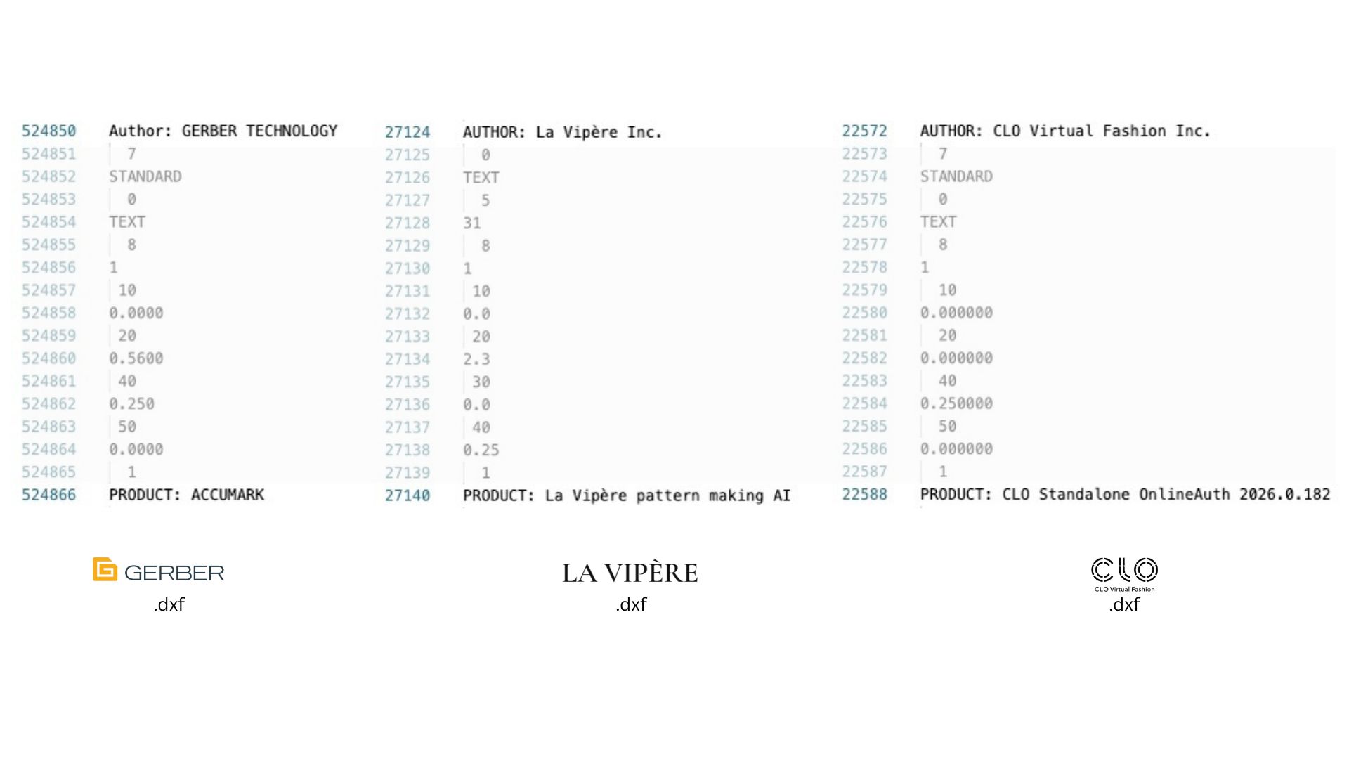
Inner DXF file view from different providers: Gerber, LA VIPERE, and CLO3D. Same extension, different export dialects.
Most workflows rely on layer conventions. Two layers are especially important:
- Cut layer: the outer contour, often including seam allowance, used by cutting workflows.
- Sew layer: the net pattern contour used for construction.
Additional layers carry internal data such as notches, grainlines, drill marks, labels, and other manufacturing annotations. Geometry is generally encoded as polylines: ordered point sequences that define each piece.
Why import fails even with standards
AAMA and ASTM conventions exist, but real-world implementations still vary by vendor. In practice, each CAD system has its own DXF writer and parser behavior.
That means tiny structural mismatches can break import:
- header tokens in unexpected positions,
- different layer names or numeric ids,
- entity ordering differences,
- style or table sections that a strict parser requires.
So standards define a family, but each software still expects a specific dialect.
The practical AI workaround
Keep one known-good DXF exported from your target system. When a client file fails, compare the two files structurally and let AI generate the conversion script.
The workflow:
- Use a valid reference DXF from your destination CAD as the target schema.
- Ask AI to Diff that file against the incoming client DXF.
- Ask AI to identify structural differences in headers, table sections, layers, and entity grouping.
- Ask AI to create a deterministic mapping script that rewrites incoming files into your target flavor.
- Validate import, then reuse the AI generated script for the same client/source system.
This is exactly where AI helps: it parses large text DXF files, spots repeating mismatches, and writes the conversion script for you. In many cases, this takes less than 30 minutes to reach a working conversion, and then you reuse the same script every time files come from that client or software source.
From one-off fixes to repeatable interoperability
In early production workflows, conversion often starts manually: ask the client for a sample file, inspect it, and make a custom exporter or transformer. With AI writing the script from the structural diff, that process shifts from painful trial-and-error to a repeatable pipeline.
If geometry is correct, format mismatches should not be a deal breaker anymore. The bottleneck shifts from vendor release cycles to your own conversion layer, which you control.
Takeaway
DXF interoperability in fashion is mostly a data plumbing problem. Treat each parser as a dialect, keep a known-good reference file, and let AI automate the structural mapping work.
You do not need to wait for CAD providers to align their exporters. You can bridge systems yourself and keep production moving.